
Circular Gears
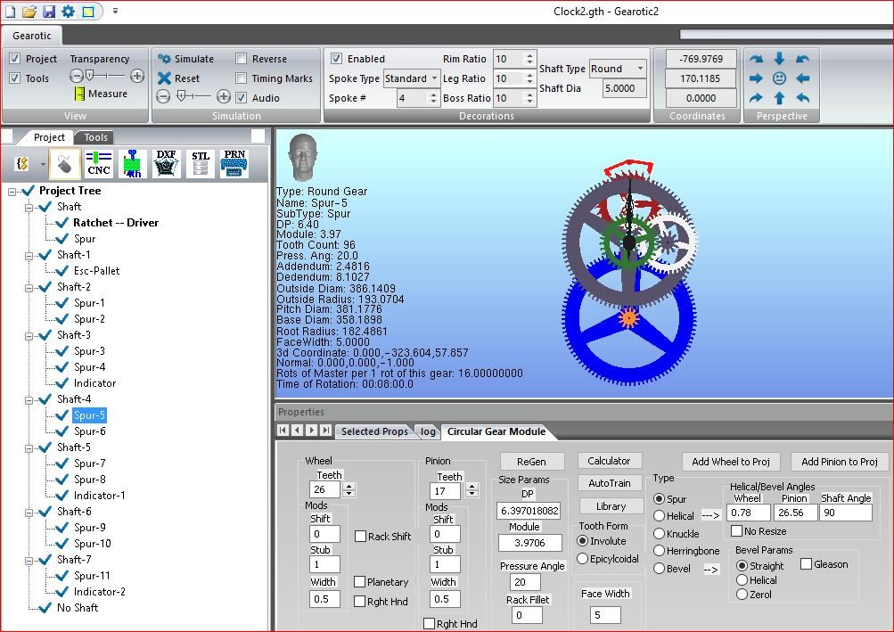
Gearotic CAD Project Screen
Within the Circular gear module of Gearotic CAD, a wide variety of gear type exist, that may be generated to correspond to user requirements. Software supports tooth formation for spur gears, helical, herringbone, bevels, and our very own knuckle gear for those 3D printers. Of course all gears fall within ISO specs by default, however for the real world, additional tools exist should slight tweaking be required to help mate new with old gear design. Gearotic CAD can vary tooth form to go from involute to epicycloidal, with configurable offsets. A series of adjustable parameters exits for each type, allowing full configuration of your gear including ring or planetary gear.
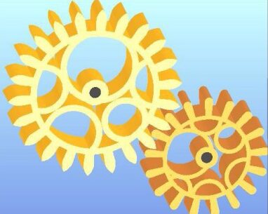
Epicycloidal gear set

Epicycloidal meshing
Gear train
Inside Gearotic CAD, the Circular Gear Module basically enables the tools nessecary for the drawing platform to generate any circular gear. These modules becomes the fundamental elements to achieve what users need.
Helical or Bevel form gears can be outputted from Gearotic CAD as Straight, Helix or Zerol formats. Additionally we offer the Herringbone and Knuckle gear for you to play with too. These types of gears can be exported as STL’s for printing, real simple and easy. However, it only becomes possible to mill these type of gears with a 5 axis milling tool. We have however found a way, if you make the blank, to do it using only 4 axis. I strongly suggest you visit our GearHead Forum for more info on this technique, but it does work.
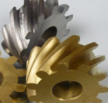
Helical gears
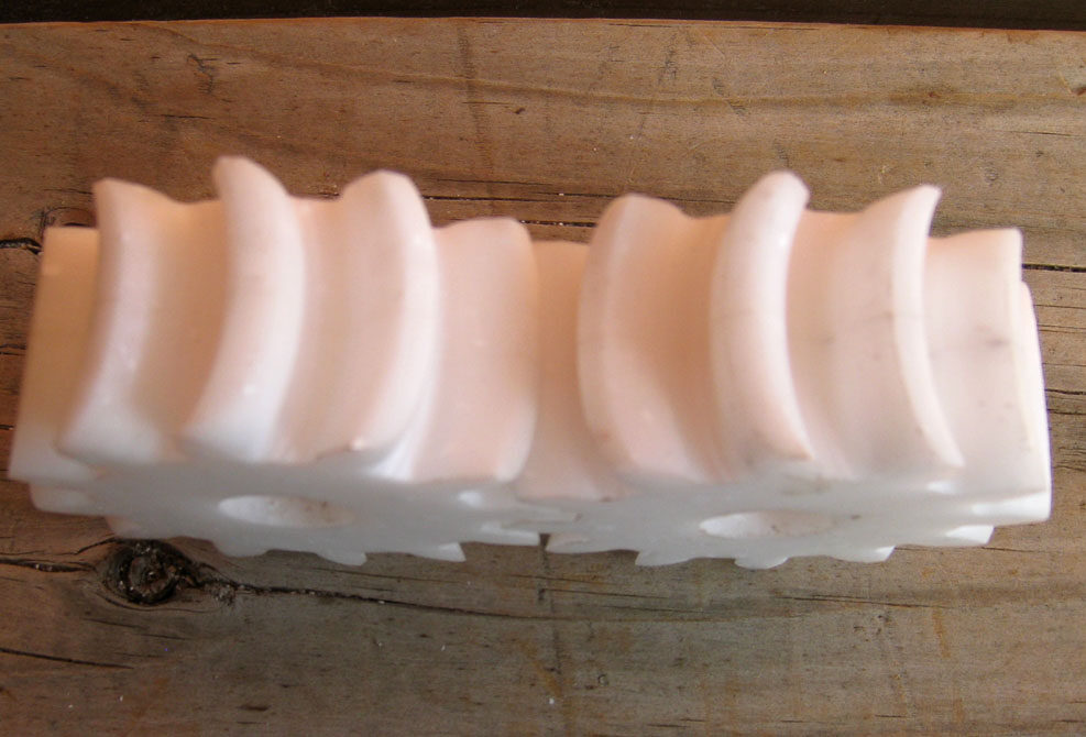
Knuckle gear
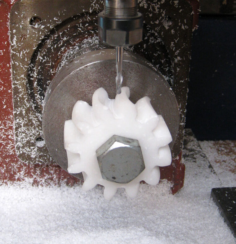
Knuckle gear being cut
The creation of Planetary gears inside Gearotic CAD is possible, however a rule exist to be possible. Rule is, you must select a larger number of teeth on the primary outside wheel, in order to have enough clear distance to properly mesh the inner pinion wheel throughout. Keep the rule, planetay gears will work fine, ignore it you might run into difficulties. Planetary gears are used everywhere these days in design and functionality, very popular amongst hobbyist. Gearotic CAD offers a huge variety of tools and options here to help you get started and design your own.
Planetary gears
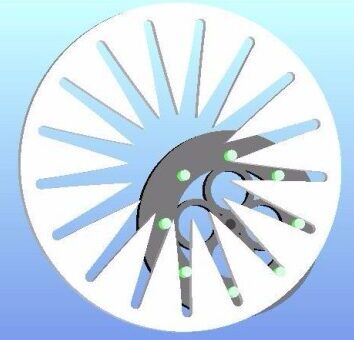
Planetary version of a Lantern Gear

Sprocket Gear
Gear train
Gearotic CAD Circular Gear module supplies users with necessary tools to design gears defined in this category. Designs may consist of spur gears, planetary, helical, herringbone, bevel and knuckle gears. Our simple to use front end design allows a gear to become a 3d object once the “Add Wheel To Project” or “Add Pinion To Project” gets pushed. This creates and implements the gear within Gearotic as a simulation object and gets added to the “Project Database”, Simply repeat the process to design your own gear train and all gears inside can be individually analysed from that point forward. A few helpful features also exist in the software. If you are adding or meshing a gear on to another gear, the gear placement screen will become active. It will draw a circular ring around the gear you’re adding a gear to, displaying the shaft centerline placement to help visualize what’s happening. You may then use your mouse to rotate the gear around until you are satisfied with placement, click once more to drop and lock in place. All of our gears are proper involutes using standard industry formulations with adjustable overrides. We invite you to review video’s made, be aware that the look of Gearotic platform may have change over time as it continues to develop , which isn’t important, what is important is to know how the gear gets generated and becomes part of Gearotic project, which in return remains the same as in newer revisions.
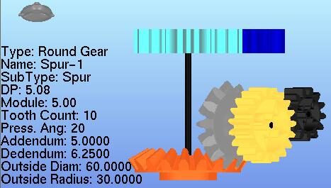
Gear train top view plane
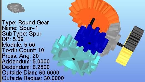
Gear train oblique view
Click here to view our circular gear part1 tutorial video on YouTube.
Click here to view our circular gear part2 tutorial video on YouTube.
Click here to view our Auto Train tutorial video on YouTube.
All rights reserved to: Gearotic Motion CAD
Email: support@gearotic.com
Nova Scotia, Canada